![]()
Disclaimer: Although every effort has been made to ensure the completeness and fit of this upgrade kit, some adjustments may be necessary due to variations in the assembly of your particular application. Please verify that all parts listed are present in your shipment and that all parts and materials are in their proper condition before installing the upgrade on your vehicle. All assemblies should be test-fitted before installing and cleaned thoroughly.
 |
 |
 |
 |
 |
 |
|
|
| [1] | Disconnect the battery. | |
| [2] | Raise the car and support with jack stands. | |
| [3] | Remove the Passenger-side front wheel. | 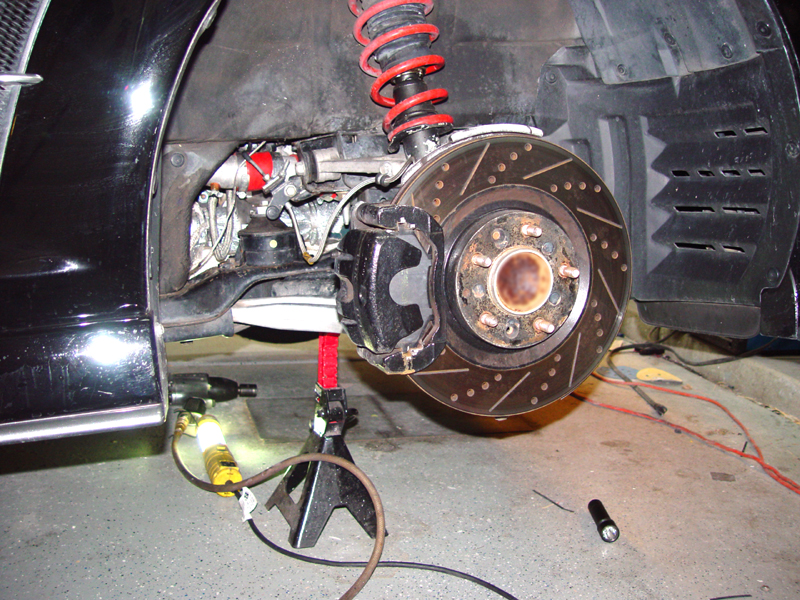 |
| [4] | Drain the oil and remove the hose and drain bolt fitting. Plug the drain hole temporarily with the OE drain bolt. | 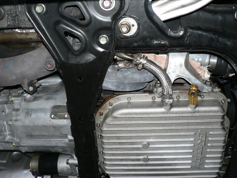 |
| [5] | Remove the (2) 17mm and (1) 19mm bolts from the passenger-side of the front crossmember. | |
| [6] | Remove the (2) 17mm bolts from the other side of the crossmember, but only loosen the 19mm. This will allow the crossmember to swing out of the way. | 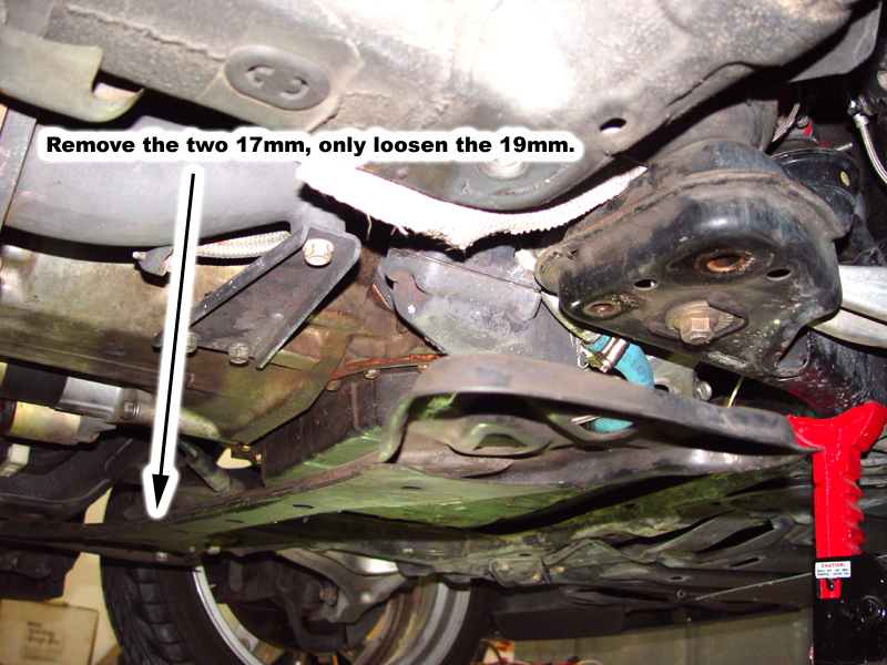 |
| [7] | Remove the middle tunnel cross brace by removing the (2) 14 mm bolts from the passenger-side and loosening the (2) 14mm bolts on the driver-side and sliding brace out. | 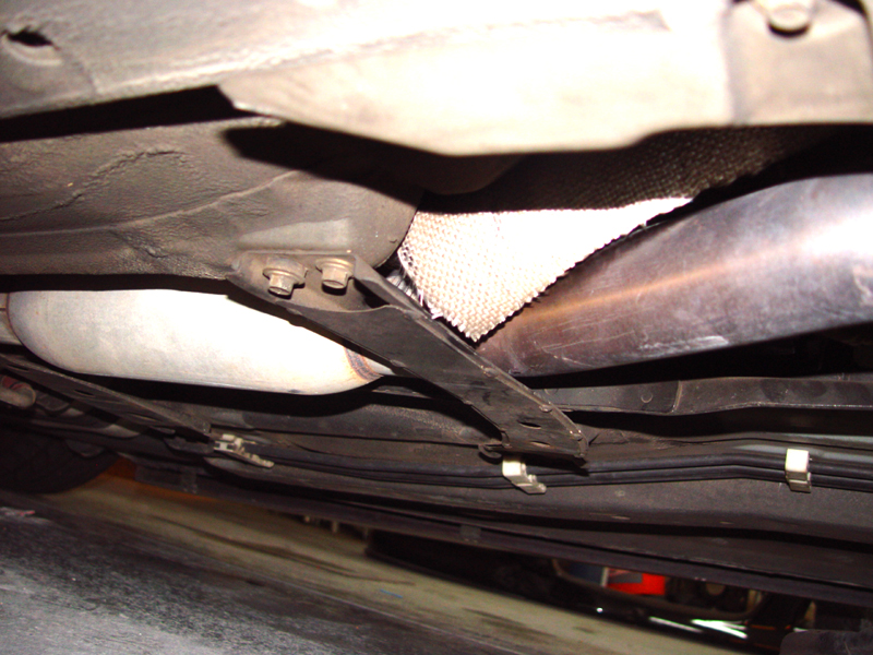 |
| [8] | Remove the downpipe support brace by unbolting the (3) 14mm bolts. | 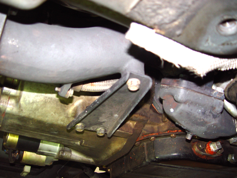 |
| [9] | Place a floor jack under the front right corner of the oil pan and, with some scrap lumber as protection, lift the jack until there is light upward pressure on the motor. |  |
| [10] | Remove the 14mm bolt from the top of the passenger-side motor mount and the 14mm bolt and 14mm nut on the sides of the motor mount. | |
| [11] | Raise the jack under the motor until the motor mount bracket clears the motor mount and remove the motor mount from the car. This may be easier if you remove the 12mm bolt from the brake line bracket directly above the mount. | 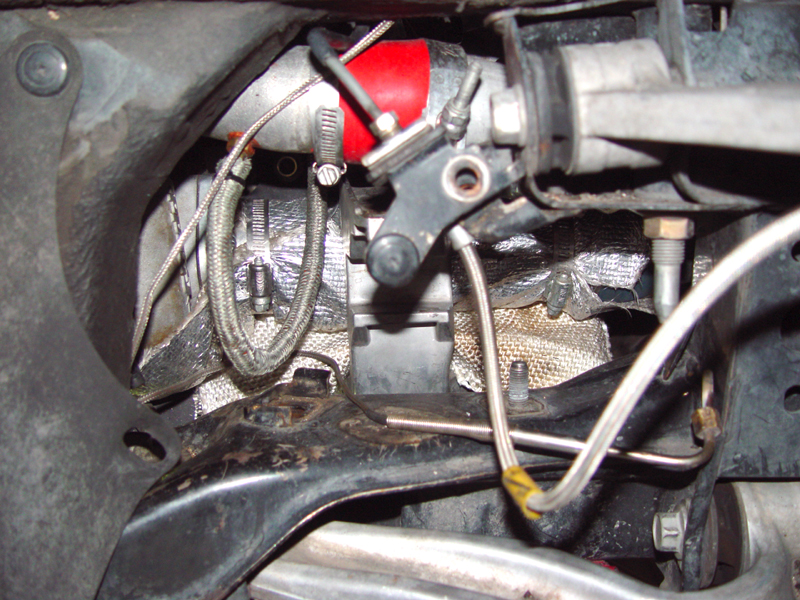 |
| [12] | Remove the front oxygen sensor with a 22mm crow's-foot wrench. Place it out of the way on top of the transmission. | |
| [13] | Unbolt the air pump discharge hose from the downpipe by removing the 10mm nuts. From the top of the engine bay, remove the hose clamps and the 1" rubber hose from the secondary air valve and the air pump. Remove the vacuum line from the valve and block it with an appropriate plug. Remove the 10mm blot that holds the valve bracket to the thermostat housing and remove the secondary air hose assembly from the vehicle. Store the air hose - you will not need it again. | 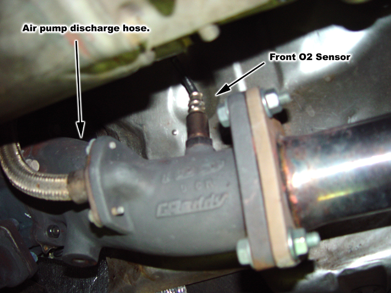 |
| [14] | Remove the hose clamps that hold the turbo inlet pipe silicone coupler the two 10mm bolts from the inlet of the turbo and remove the pipe. Keep the clamps and the coupler handy, but place the tube in storage along with it's gasket and the two 10mm bolts. You won't need them. | |
| [15] | Remove the (2) 17mm bolts and (1) nut that hold the engine mount bracket and then remove the bracket. When you do manage to get the bracket out, remember the sequence of turns that it takes - you will need to do that in reverse to get the bracket back in and it is a bit of a puzzle. I usually pull it towards the outside and then rotate is counter-clockwise as viewed from the wheel well. | |
| [16] | Remove the 12mm bolt that holds the wheel speed sensor wire and the first charge pipe (the one that goes from the turbo discharge to the intercooler). | 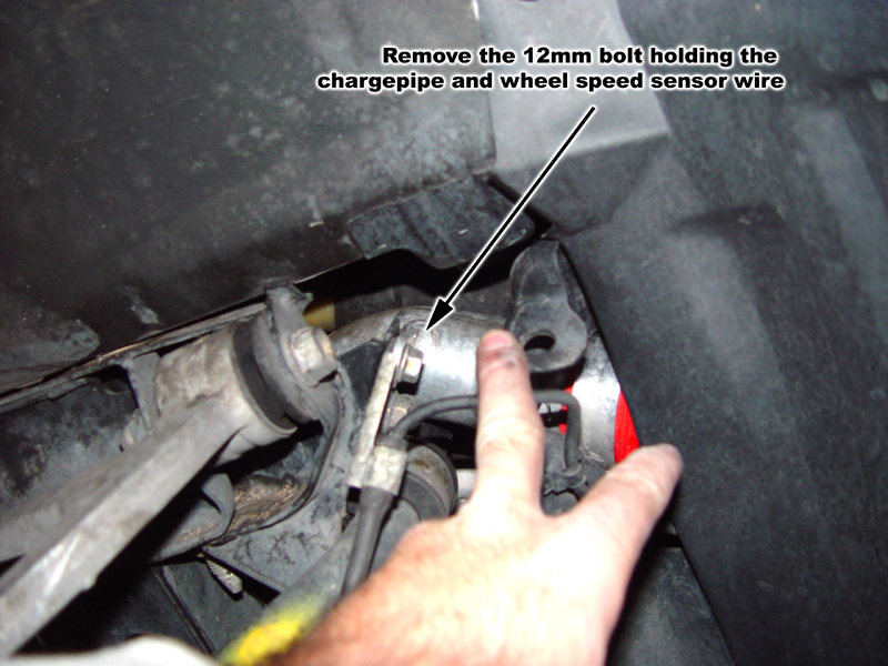 |
| [17] | Remove the hose clamps and the silicon coupler from the junction of the turbo discharge pipe and the first charge pipe. | |
| [18] | Unbolt the discharge pipe from the turbo outlet and from the intercooler junction pipe and remove from the car. This pipe will be modified later. | 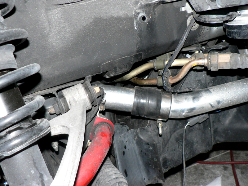 |
| [19] | Unbolt the flange of the CAT/midpipe from the downpipe and lower the exhaust. | |
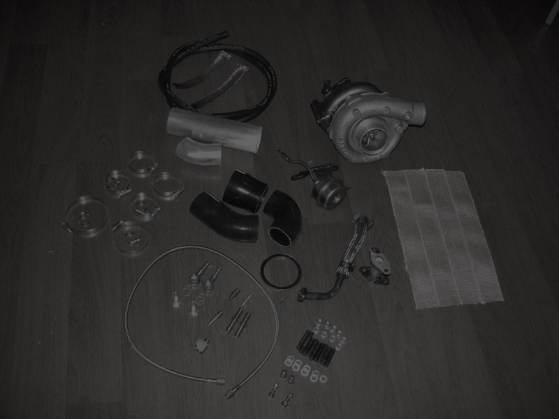
| [20] | Remove the (5) 12mm nuts holding the downpipe to the turbo and remove the downpipe | 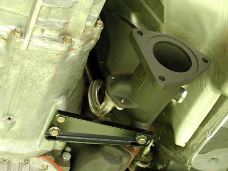 |
| [21] | Lower the floor jack holding the engine to make access to the turbo easier. | |
| [22] | Remove the oil drain fitting from the turbo by removing the (2) 10mm bolts. | 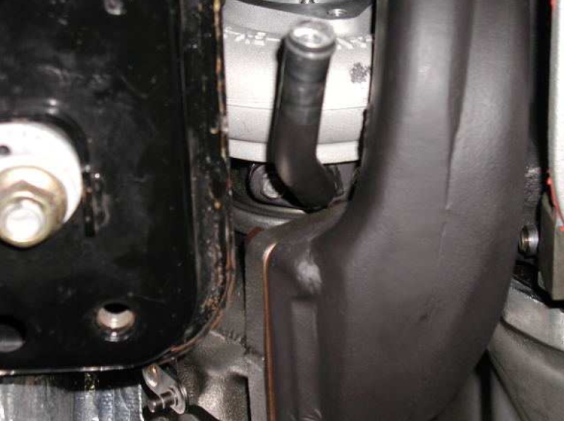 |
| [23] | Remove the (4) 12mm nuts holding the turbo to the manifold. | |
| [24] | Remove the (6) 14mm nuts holding the manifold to the engine. | |
| [25] | Lift up the turbo off of the manifold and remove the manifold carefully. | |
| [26] | Lower the turbo and remove the AN-4 oil hose. | 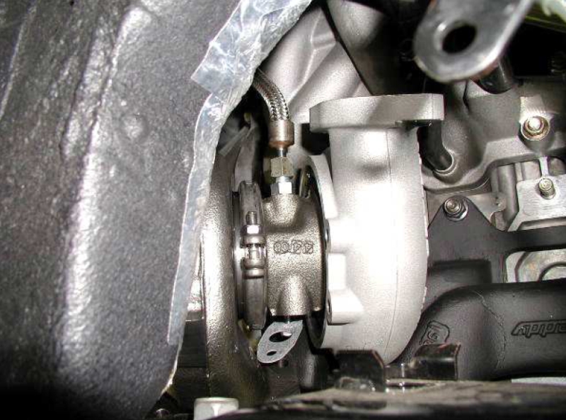 |
| [27] | Remove the turbo and place somewhere out of the way. | |
| [28] | At the "T" fitting at the oil pressure sender, remove the oil hose to the turbo, disconnect the pressure sender connector and remove the "T" from the engine. | |
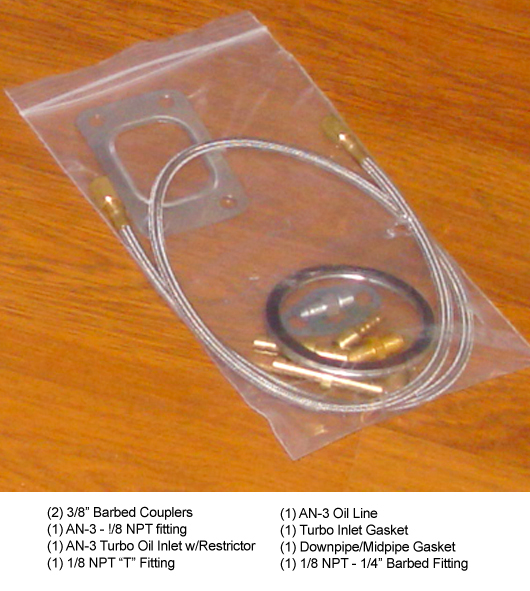
| [29] | Carefully remove the Garrett turbo from the upgrade kit from its packaging and place on a work surface. | |
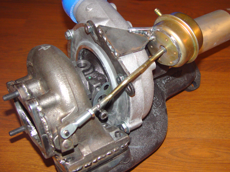
| [30] | Screw in the (5) studs ((3) 40mm and (2) 50mm) on the turbine outlet flange. The two longer studs go in the indicated locations. | 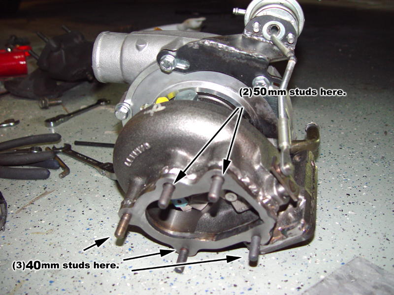 |
| [31] | Apply a thin layer of gasket cement or sealant on one side of the oil drain gasket and place over the oil drain outlet on the bottom of the turbo center section. Screw in one of the M8 cap head screws into the threaded hole closest to the turbine inlet, leaving about 1/4" of the thread exposed. | 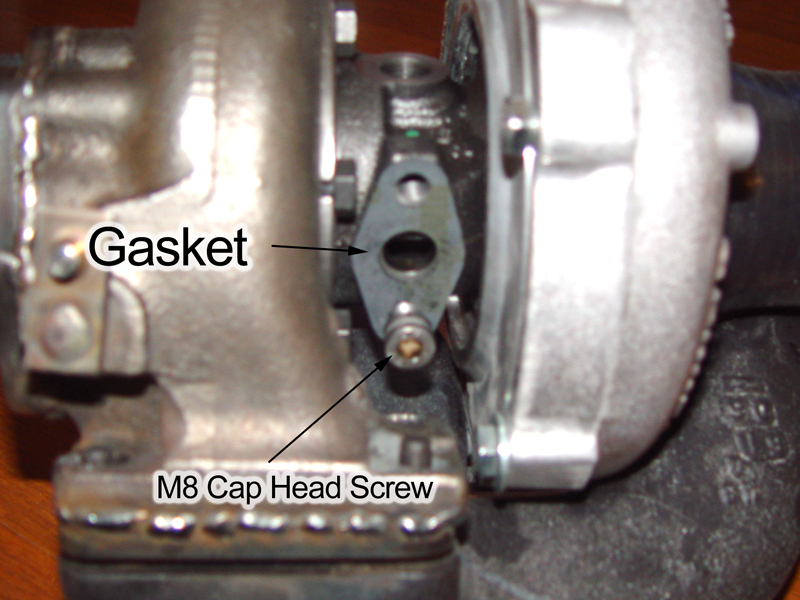 |
| [32] | Screw the (4) 45mm studs into the exhaust manifold turbine inlet. | 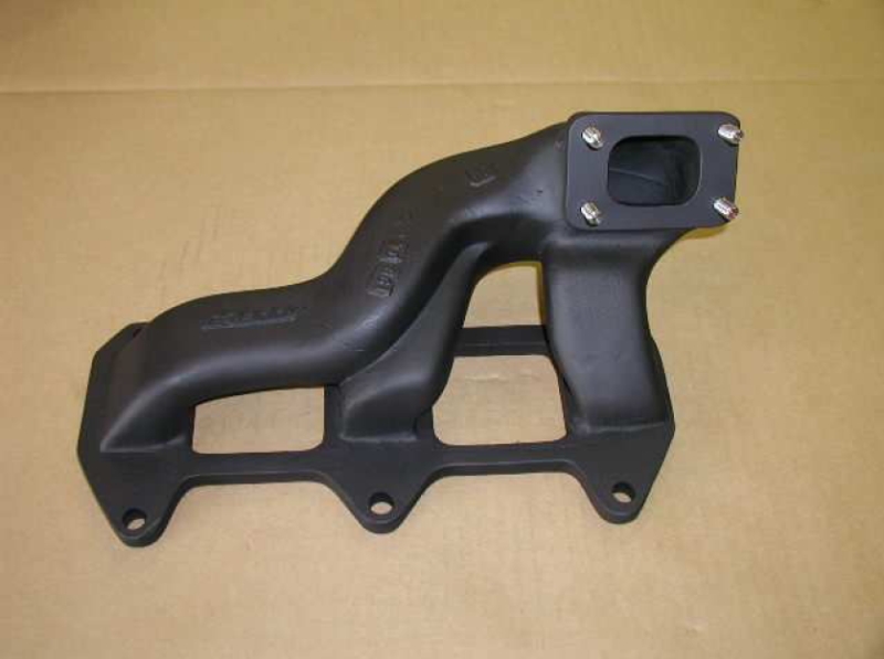 |
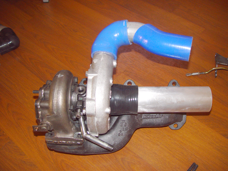
| [33] | Assemble the two water fittings as shown and attach to the turbo so that they are pointing straight up between the turbine and the compressor housings. | 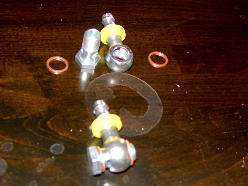 |
| [34] | Screw in the oil inlet fitting. It is a "flare" fitting, so it does not need any sealant or high torque. | 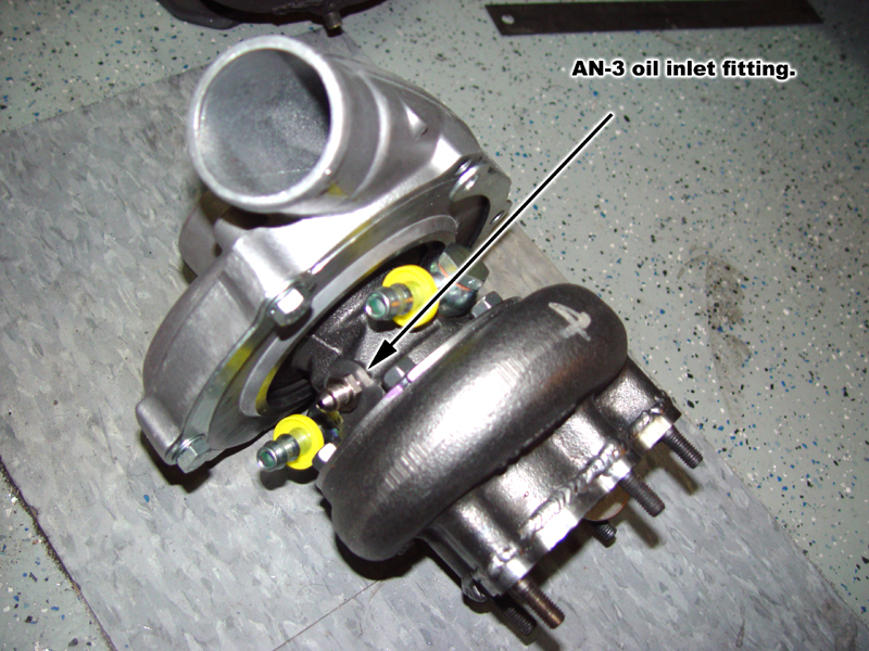 |
| [35] | Screw the oil pressure sender into the leg of the "T" directly opposite the male threaded side and the AN-3 fitting into the other opening. Use a little bit of sealant on all of the threads. Screw the "T" into the engine. Attach one end of the oil supplied line to the AN-3 fitting and run the line up and over the transmission so that it comes down where the turbo will sit. | 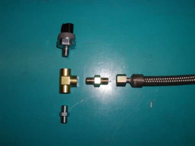 |
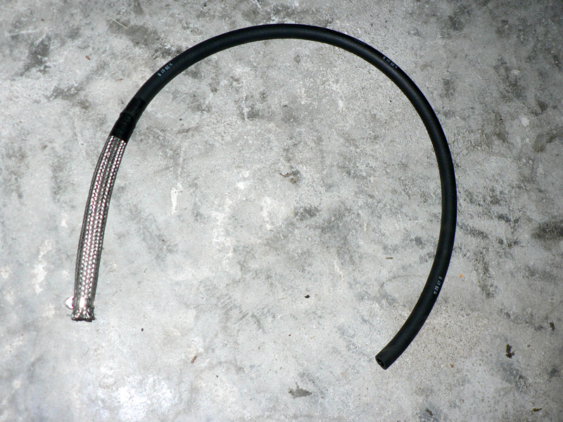
| [36] | Cut the steel braided hose shield into
three 6 inch sections. Slide two of the sections onto each of the two
supplied water hoses along with one small hose clamp. Using silicone
lubricant, slide each of the hoses onto the water fittings on the turbo
and secure them with the hose clamps over the braided shield. Pull the
braid tight up the hose and secure it with a few inches of electrical
tape. |
 |
| [37] | With an appropriate cutting tool, remove 2" from the turbo end of the first discharge pipe remove in step [18]. Reinstall this pipe, but do not attach it with the bolt yet. | 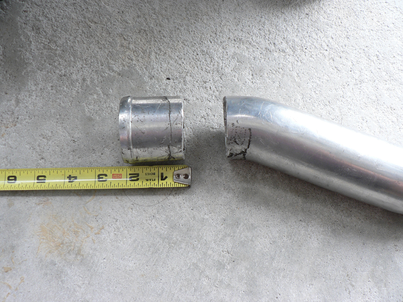 |
| [38] | While holding the turbo under the car, run the water hoses up through the space between the intake manifold and the frame rail, guiding all of the slack between the two vacuum "nipples" on the lower intake manifold. | |
| [39] | Attach the oil supply line to the supply fitting on top of the turbo. | |
| [40] | With the jack supporting the engine in its lowest position, lift the turbo up into the space where it will be mounted. This is easiest to do with the turbo oriented the way it will actually be installed. Once it is in the space, hold it through the opening where the motor mount was installed, pulling it tightly against the frame of the car. Lift the exhaust manifold up and past the turbo and onto its studs. Place one exhaust manifold nut on the center top stud and turn it just enough to keep the manifold from falling off. Allow the turbo to rest, but don't thread it onto the studs on the manifold. Check the clearance of the discharge outlet on the compressor. There should be enough room to fit the 90° silicone hose to the outlet and not interfere with the intake manifold or the frame of the car. It might be necessary to "clock" the compressor housing a few degrees in one direction or another to ensure this fit. If the turbo sits too close to the floor pan, it might be necessary to "massage" the floor pan sheet metal with a mallet to provide extra clearance, especially on cars with older motor mounts that allow the engine to move excessively right and left. | 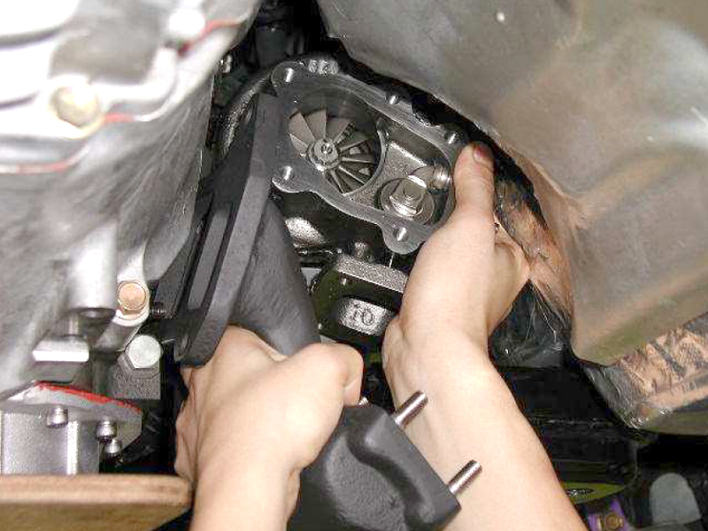 |
| [41] | Tilt the turbo forward and place the 2", right-angle silicone coupler onto the discharge flange of the compressor. place a hose clamp onto that junction, but do not tighten it yet. | 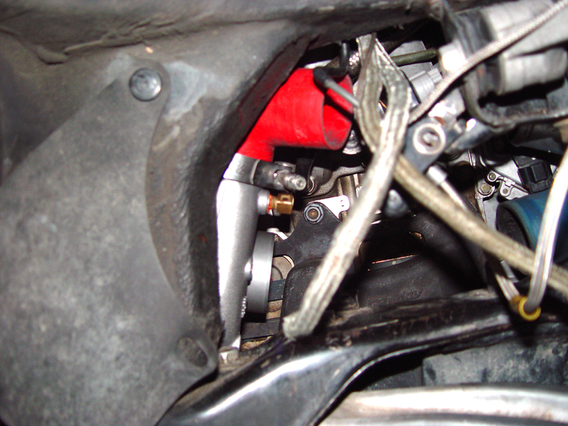 |
| [42] | Raise the jack supporting the engine up to a normal height and place the insulating "blanket" over the exhaust manifold so that it covers the entire length of the manifold. Be sure that the "copper" side is facing the manifold and the white fiberglass side is towards the turbo. (This step is shown out of the car for clarity.) Slip the turbo inlet gasket over the turbine inlet studs and lower the turbo onto the turbine inlet studs, being sure not to pinch the blanket between the flanges. As you are positioning the turbo, adjust the position of the (2) water hoses that were attached in step [36]. It is a tight fit around the compressor housing and under the lower intake manifold. Raise the jack under the engine until the turbo can sit flat on the exhaust manifold discharge flange and securely attach it with (4) low-profile12mm nuts and (4) lock washers. Be sure that the air pump discharge hose and the water fittings are correctly positioned. | |
| [43] | Smear a thin film of sealant on the mating surface of the oil drain pipe, slide the slotted opening over the previously installed M8 cap head screw and secure it to the oil discharge flange on the turbo using the other M8 cap head screw. Use a ball-end, 7/32" hex key so that you can approach the cap-head screws from a suitable angle as needed. It might be necessary to pry the motor towards the driver side of the vehicle to gain access to the cap screws as the fit is very tight. It may be possible to pull the manifold off of the engine studs with the turbo attached and move it rearward to gain better access to the cap head screws. (This step is shown out of the vehicle for clarity.) | 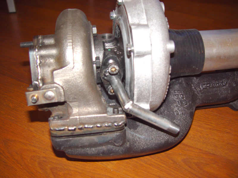 |
| [44] | Place the remaining 5 nuts onto the exhaust manifold to engine mounting studs and secure the exhaust manifold to the engine. Torque the nuts in a "cross" pattern. | |
| [45] | Place the engine mount bracket into position, but do not attach it to the motor yet. | |
| [46] | Place the 2.75" to 2.5" silicone adapter over the turbo intake and secure it with a hose clamp. Work the 2.5" upgrade kit inlet pipe into the turbo inlet coupler and the coupler to the intake piping along with two hose clamps. Once you are satisfied that the pipe is sitting squarely between the two pipes and wont interfere with the motor mount bracket, tighten the hose clamps on the inlet pipe. | 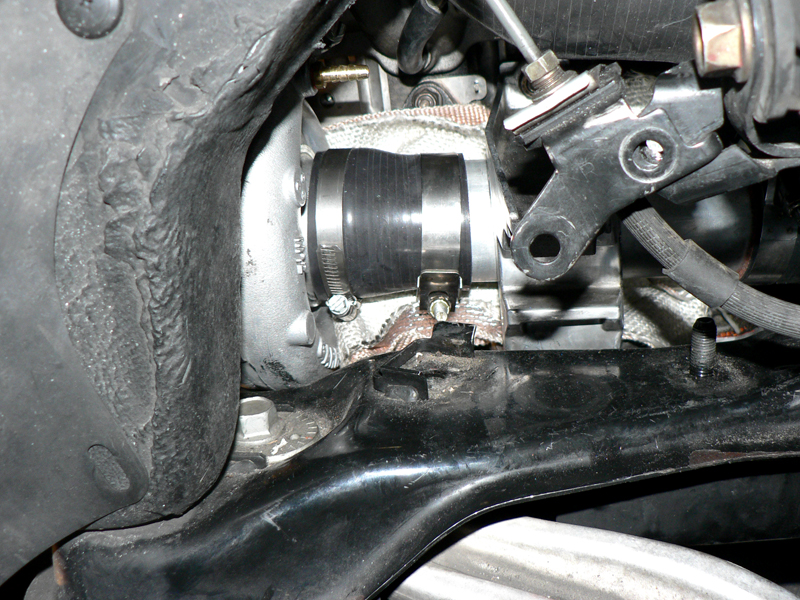 |
| [47] | Work the 2" upgrade discharge pipe and two hose clamps between the right-angle silicone discharge coupler and the silicone coupler on the first charge pipe going to the intercooler. Once you are satisfied with its position, replace the 12mm bolt holding the charge pipe and speed sensor cable to the frame and then tighten all of the hose clamps (don't forget the clamp the was put onto the discharge of the turbo with the right-angle silicone discharge coupler). (This step is shown out of the vehicle for clarity.) | 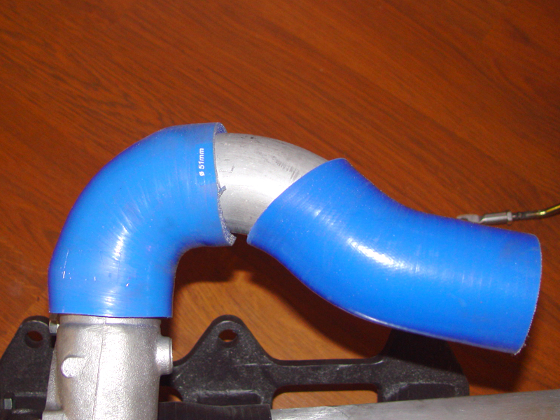 |
| [48] | Attach the engine mount bracket with the (2) 17mm bolts and (1) 17mm nut and tighten. | |
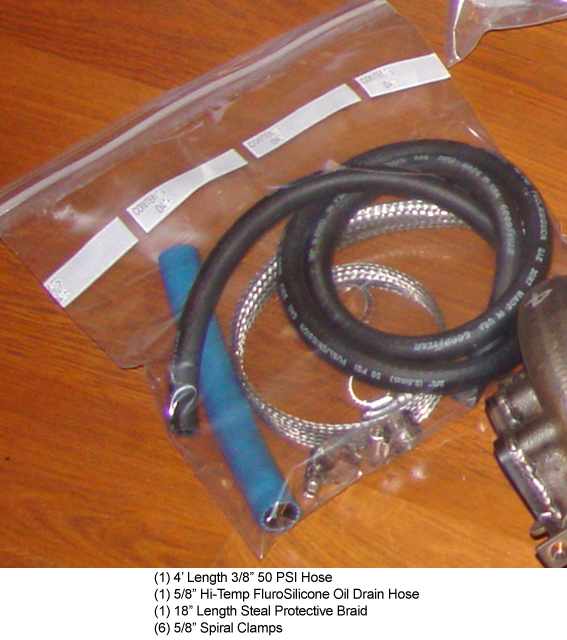
| [49] | Attach the flurosilicone drain hose and determine the amount to trim for a smooth, un-kinked bend to the drain bolt. Trim the hose and them slit the third piece of steel braid over it and secure to the oil drain pipe with a hose clamp. | 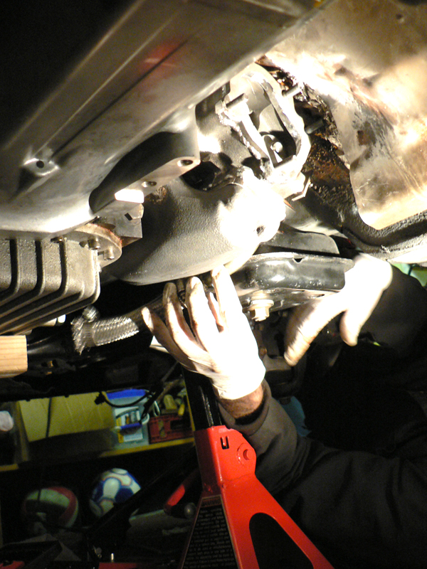 |
| [50] | Loosely fit the waste gate bracket and the (2) 13mm bolts that hold it to the back of the compressor housing. Adjust the position of the bracket so that the actuator arm has the straightest possible shot at the wastegate swing arm crank and so it does not interfere with the motor mount or the frame of the vehicle. Tighten the actuator bracket bolts. (This step is shown out of the vehicle for clarity.) |
 |
| [51] | Mount the downpipe to the turbo discharge flange with the original gasket from the GReddy kit and tighten the (5) 12mm nuts securely over (5) lock washers. | 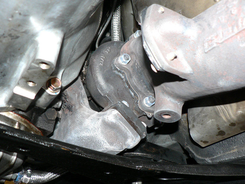 |
| [52] | Taking care not to cross-thread it, reinstall the front O2 sensor. You should turn it 4 or 5 times in the opposite direction of installation prior to threading it so that the cable has slack to unwind as it is tightened. | |
| [53] | Attach the secondary air hose blocking plate on the air pump flange on the downpipe with the (2) two 10mm bolts. | |
| [54] | Reattach the midpipe/CAT pipe to the downpipe. Be sure the new "O" gasket is not crushed or misaligned. | |
| [55] | Using a drill or ream, open up the three holes on the downpipe to transmission support brace to 9/16". | 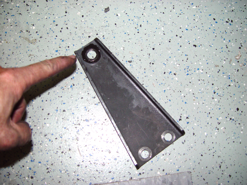 |
| [56] | Install the downpipe to transmission support brace. | |
| [57] | Raise the motor as high as possible with the jack and reinstall the motor mount. Thread the top screw first. Lower the motor onto the mount and tighten. If you removed the 12mm bolt that held the brake line, replace it now. | |
| [58] | Reinstall the tunnel cross brace under the midpipe/CAT pipe. | |
| [59] | Reinstall the front crossmember. | |
| [60] | Locate the throttle-body coolant lines. There is one that goes from the thermostat housing to the TB and another that goes from the TB to the top right of the rear rotor housing. If you intend to bypass the TB coolant lines, you will simply pull these and reroute them. If you wish to keep hot coolant flowing through the throttle body, you will splice into the line that returns coolant to the rotor housing. Pull the two lines from the turbo up and into position. Measure and cut the lines so that when they are joined to the TB lines, they are neat and transition smoothly. Splice the two lines into the selected TB lines using the 3/8" barbed couplers. If the engine is completely cool, there will be little to no coolant loss. | |
| [61] | Reinstall the passenger-side wheel, remove the jackstands and lower the car. | |
|
|
||
| NOTES | 1) It may be necessary to provide
additional clearance for the turbo by manipulating the passenger footwell
floorpan directly above it with an apropriate mallet.
2) The oil drain cap-head bolts are most easily addressed with ball-end hex keys. 3) Due to casting tolerances, the bolt holes in the GReddy downpipe may need to be slightly enlarged to allow proper fitment to the turbine discharge. 4) There have been some incremental changes in the contents of the kit and the shape of some of the parts. Please test-fit ALL parts prior to assembly. The pictures here may not represent the most current revisions. 5) All kits are test-fitted prior to shipment. If something doesn't seem to fit, take a moment to assess what may be unique about your particular installation that might cause fitment issues. |
|
©1999 - 2009 MazdaManiac.com